



Plant engineers and procurement teams often overlook power requirements when specifying level indicating controllers. These devices combine local level display, measurement input and control logic to automate tank fill and drain sequences for liquids, powders and granular solids. Get the power supply wrong, and you face unstable readings, intermittent alarm faults, or premature hardware failure. Many projects hit delays at commissioning simply because the power budget and wiring topology were not reviewed early in the selection process.
A level indicating controller reads input signals from level sensors, shows real-time tank level locally, and triggers relays to operate valves, pumps or warning alarms. The core power draw depends heavily on the connected sensing technology, built-in features, operating environment and wiring architecture (2-wire loop-powered versus 4-wire independent supply).
Core Wiring Topology: 2-Wire Loop-Powered vs 4-Wire Controllers
2-Wire Loop Powered (4-20mA)
Two-wire loop power is the most common setup in process plants. The controller and transmitter share the same DC power over the signal cable. This configuration is simple to install and uses less field wiring. Most 2-wire systems run on 12–28 V DC, with 24 V DC being the industry standard.
There is a hard limit on available power in loop-powered designs. The total current in a 4–20mA loop cannot exceed 20mA, so power consumption stays low. These units work well for basic indication and simple relay alarms, but they cannot support heavy loads such as large backlit screens, continuous data logging or high-power wireless modules. If you add too many auxiliary functions, the loop voltage will drop and the system will stop working reliably.
4-Wire Independent Power
Four-wire controllers separate the power supply from the measurement signal. Two wires deliver mains or DC power, and the other two carry the 4–20mA measurement signal. This setup gives higher available power for larger displays, data logging, Modbus, Ethernet, Wi-Fi and multiple relay outputs.
4-wire models can accept either 24 V DC or universal AC input (85–264 V AC). This is the preferred choice for central control panels, tank farm control cabinets and complex automation systems. The tradeoff is extra wiring cost and additional surge protection requirements in hazardous areas.

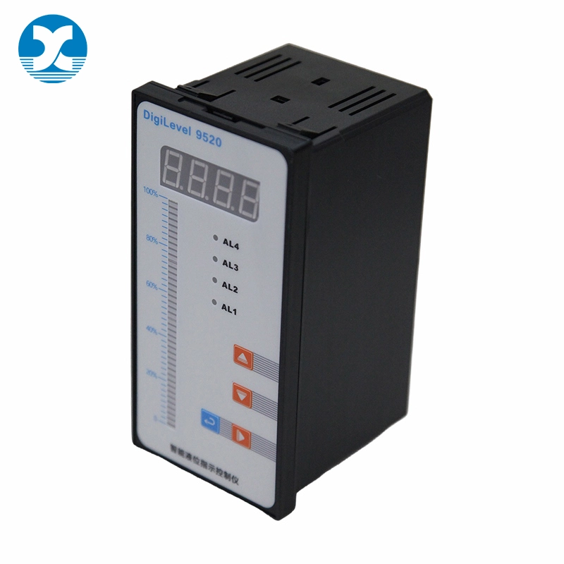
Power Needs by Level Sensing Technology
Ultrasonic Level Indicating Controllers
Ultrasonic controllers send acoustic pulses toward the material surface and calculate distance based on echo return time. Most ultrasonic systems operate on 12–24 V DC. Many compact field-mounted units run well on low power, making them suitable for remote sites powered by solar panels and rechargeable battery banks.
Power draw is low because the transducer only pulses periodically rather than transmitting continuously. The main power spikes happen during the ultrasonic burst and signal processing. Keep in mind that heavy condensation, foam or dust can increase signal processing load slightly, though the nominal power rating rarely changes. These are widely used for water, wastewater and non-foamy liquid tanks.
Radar Level Indicating Controllers
Radar instruments emit high-frequency radio waves to measure level. Unlike ultrasonic units, radar transmitters and their matching indicating controllers demand higher power for signal generation and high-speed echo processing. Basic FMCW radar systems typically use 24 V DC in 4-wire configurations. High-performance radar for high-pressure vessels or long measuring ranges may require stable 24–48 V DC or universal AC power.
2-wire radar transmitters exist, but they limit the controller's available features. If you need local display, multiple relays and remote communication, almost all high-precision radar installations use 4-wire power. Radio signal processing creates constant power draw, so power supply ripple and voltage drop along long cables must be carefully calculated during design.
Capacitance Level Indicating Controllers
Capacitance systems measure shifts in dielectric constant between the probe and vessel wall as material covers the sensing element. Their electronics are simple and low-power. Most capacitance-based indicating controllers run on 12–24 V DC.
They fit tight installations where power availability is constrained. Power consumption remains steady unless the probe needs active heating for high-humidity or condensing environments. Heated probe variants will increase power requirements and usually require a dedicated 4-wire supply. Capacitance controllers work well for powders, granular solids and many liquid storage tanks.
How Onboard Features Change Power Consumption
Local Display and Backlighting
Basic segment displays use minimal power. Full colour, high-brightness backlit screens draw noticeably more current. If your controller runs on solar or battery power, avoid high-bright displays unless you size the battery and solar array to match the increased load. Many models offer dimming or sleep modes to reduce power use during idle periods.
Alarms and Relay Outputs
Relays are electromechanical switches and require extra power when energized. Simple LED visual alarms add very little load. Audible buzzers or horn outputs draw more current, especially continuous high-volume alarms.
Safety critical overfill or low-level pump stop relays need a stable power source. In loop-powered systems, you must calculate the combined current draw of all relays before finalising your design. Overloading the 4–20mA loop is a common field mistake.
Data Logging and Communications
Data logging uses power for memory chips and continuous sampling. The bigger impact comes from communication interfaces. Bluetooth has low power demand. Modbus RS485 adds a moderate load. Wi-Fi and Ethernet consume significantly more power, and they almost always require a 4-wire supply.
For remote tank sites using cellular IoT modules, peak power draw happens during transmission. Your power supply and battery bank must handle these short current spikes, not just average consumption.
Environmental Factors That Shift Power Requirements
Ambient temperature affects electronic component behaviour. At extremely low temperatures, some circuits draw slightly more current, and LCD displays slow down. Controllers rated for cold service may include internal heating elements, which substantially raise total power consumption.
High humidity, corrosive atmospheres and vibration do not directly increase power draw, but they demand better power supply protection. Surge protection, noise filters and isolated power modules become necessary to avoid damage from electrical transients on industrial power lines.
For explosive classified zones, power must comply with intrinsic safety standards. Intrinsically safe designs limit available voltage and current, which restricts what features you can add. You cannot connect high-power communications or large relay loads without proper safety certification.
Available Power Supply Options for Level Indicating Controllers
Battery and Solar Power for Remote Sites
Battery power works for low-draw 2-wire controllers in locations without grid power. Rechargeable batteries paired with small solar panels are a standard solution for remote well tanks, rural water storage and off-grid bulk bins.
Always size the battery for the worst-case season, such as short winter daylight hours. Account for the controller baseline draw plus periodic transmission spikes if using wireless data transfer.
DC Power Adapters and Industrial DC Supplies
24 V DC industrial power supplies are the most common choice for panel-mounted controllers. These units deliver clean, regulated DC voltage with overload and short-circuit protection. Avoid cheap consumer adapters; industrial power supplies handle voltage fluctuations and electrical noise on factory floors.
Universal AC Power
Universal AC input (85–264 V AC) is typical for cabinet-mounted 4-wire controllers. This option is convenient when you have mains power near the control panel. It is widely used in water treatment plants, chemical processing buildings and permanent tank farm control rooms.
Power Considerations for Tank-Side Monitors
Tank-side monitors often pair with level indicating controllers to show level readings right beside the vessel. Visit this page to learn more: /display-controller/tank-side-monitor.html. Tank-side displays normally run on 12–24 V DC and have low power draw, similar to basic indicating controllers.
When you daisy-chain multiple tank-side displays, total current adds up. The main power supply must support the combined load of the controller plus all remote tank-side monitors. Long cable runs also introduce voltage drop, which you must calculate to keep every display within its rated operating voltage.
Common Power-Related Field Issues
Undersized power supplies and excessive voltage drop over long cables create unstable readings. When voltage falls below the controller minimum operating threshold, the unit can reset randomly or show erratic level values.
Electrical noise from nearby motors and variable frequency drives can interfere with low-voltage DC supplies. Use shielded cable, proper grounding and isolated power supplies in these environments.
Another frequent error is trying to fit high-power features such as Wi-Fi or multiple heavy relays onto a 2-wire loop-powered controller. The loop cannot deliver enough current, leading to intermittent faults that are hard to troubleshoot.
Selection Checklist for Power Requirements
Confirm wiring topology: 2-wire loop-powered or 4-wire independent supply.
Identify the connected level sensor technology and its power rating.
List all required features: display type, relays, logging, communication protocols.
Measure cable length and calculate voltage drop across field wiring.
Check ambient temperature; determine if internal heating is required.
Verify hazardous area classification and intrinsic safety limits.
Confirm available site power source: solar/battery, 24 V DC, or mains AC.
Conclusion
Power requirements for a level indicating controller are not one-size-fits-all. The key variables are 2-wire versus 4-wire architecture, sensing technology, optional functions and site operating conditions. Ultrasonic and capacitance systems tend to run on low 12–24 V DC power. Radar and controllers with wireless, data logging or multiple relays usually need a 4-wire supply with higher power capacity.
Remote off-grid sites can use solar and battery setups, while control room installations commonly use regulated 24 V DC or universal AC supplies. Many avoidable commissioning faults come from skipping power budget and voltage drop calculations before purchase.
If you are specifying a level indicating controller for your tank application, share your sensor type, required outputs, cable length and available site power. Our engineering team can validate the power budget and recommend the correct controller and power supply configuration.Reach out anytime for technical support and product selection help.
References
- IEC 60546-1, Industrial process measurement and control controllers – Performance test methods
- ANSI/ISA-50.00.01, Compatibility of Analog Signals for Electronic Industrial Process Instruments
- IEC 60654-2, Industrial process measurement and control equipment – Operating conditions, power supply
- Manufacturer operation manuals for level indicating controllers and level transmitters
- ISA recommended practice for power distribution and wiring in process measurement systems


