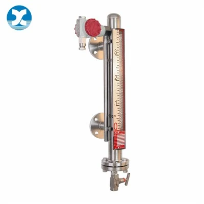
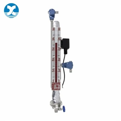
Installing a magnetic flapper level gauge looks straightforward on paper - bolt the chamber to the tank flanges, open the isolation valves, and you're ready to take readings. In practice, though, a surprising share of post-installation headaches trace back to small, easy-to-rush steps that first-time installers skip.
I've walked through enough on-site service calls for stuck floats, weeping flanges and erratic readings to know: most of these issues don't come from a manufacturing defect. They come from cutting corners on pre-install checks, opening valves in the wrong order, or skipping basic alignment steps. Get these details right, and a magnetic gauge will run reliably for a decade or more with minimal upkeep. Get them wrong, and you'll spend weeks chasing intermittent issues that never seem to have a clear cause.
This guide covers the full installation workflow from unboxing to commissioning, calls out the pre-install checks you should never skip, and breaks down the most common beginner missteps that create unnecessary downtime. You won't need specialized instrumentation tools - just standard site hand tools, a little patience, and attention to the small details.
Pre-Install Checks You Can't Afford to Skip
Good installation starts before you pick up a wrench. A few minutes of verification up front avoids the frustration of lifting a heavy gauge into place only to find mismatched flanges, shipping damage, or a mounting spot that's bound to cause problems down the line.
Unbox and inspect every component first
Lay all parts out on a clean work surface and cross-check them against the packing slip before you carry anything to the tank.
- Inspect the chamber body, process flanges, indicator rail and scale for dents, scratches or transit damage. If you find concealed damage, document it and report it to the freight carrier right away.
- Locate the float. Most units ship with the float inside the chamber, held in place by a plastic shipping clip or foam restraint. This is the single most forgotten step on first-time installs. I've lost count of service calls where the gauge wouldn't move at all, and the fix was reaching in through the drain valve to pull out a tiny plastic lock.
- Confirm float orientation. Most floats have a faint "TOP" stamp on one end. It must face upward for the internal magnets to align correctly with the external flapper strip.
- Run a handheld calibration magnet once along the full indicator rail before mounting. Transit vibration often scatters a handful of flappers out of position; resetting them early confirms the full strip works correctly before you bolt the gauge in place.
- Double-check flange size, pressure rating and wetted material against your tank connections. Mismatched flanges are an expensive, time-consuming mistake to fix once the gauge is already lifted into position.
Verify the mounting location is suitable
Not every spot on a tank side wall works well for a magnetic gauge.
- The chamber must be installed vertically. Even a 3–4° tilt is enough to make the float drag against the inner chamber wall. At first you'll just see sluggish response; over months, friction wears down the float coating and leads to consistent sticking. Keep a spirit level handy to confirm plumb as you tighten the bolts.
- Make sure isolation valves are planned for both upper and lower process connections. These let you service or remove the gauge later without draining the entire tank - a feature that pays for itself the first time you need to do maintenance.
- Keep at least one meter of clearance from large motors, transformers, magnetic separators and other strong magnetic field sources. Close-proximity interference can scramble flapper readings and weaken coupling strength over time.
- Position the indicator side toward an accessible walkway or platform. There's no point in a high-visibility display if no one can safely read it during routine operator rounds.
Gather tools and confirm safety prep
You don't need specialized equipment, but having everything on hand makes the job go much smoother:
- Open-end wrenches or a socket set matched to your bolt size
- A torque wrench (highly recommended) for even flange tightening
- Spirit level
- Handheld calibration magnet
- Gaskets matched to your process medium (PTFE for corrosive service, compressed fiber or graphite for general use)
- Standard site personal protective equipment
- Confirm lockout/tagout procedures are followed if you're tying into an active process line

Step-by-Step Installation Procedure
Follow this order, and you'll avoid 90% of the most common installation issues.
1. Mount isolation valves (if not already in place)
If your tank nozzles don't already have shutoff valves, install them first. Match their flange rating and gasket material to the gauge itself. Test that both valves open and close smoothly before moving on.
2. Prep flange faces and position the gasket
Thoroughly clean both mating flange faces. Any leftover old gasket material, dirt, scratches or burrs will create leak paths. Set the gasket centered exactly on the bolt hole pattern. Take an extra second to confirm the gasket material is compatible with your process fluid - a mismatched gasket is a guaranteed leak and a safety hazard.
3. Align the gauge chamber and hand-thread all bolts
Lift the gauge into position. For longer chambers, use a lifting strap or temporary support to avoid putting strain on the lower flange during alignment.
- Line up bolt holes evenly. Never force the gauge into alignment with a pry bar - piping stress will warp the chamber over time and cause the float to bind.
- Hand-thread every bolt first to confirm alignment is correct. Do not fully tighten any bolt at this stage.
- Double-check vertical alignment with a spirit level. Add thin shims behind the flange if needed before you torque anything down.
4. Tighten bolts in a crisscross star pattern
This is the step most beginners rush, and it's the number one cause of flange leaks.
- Tighten gradually in 2–3 passes, following a star / crisscross sequence, until you reach the specified torque value.
- Never tighten one bolt all the way before moving to the next. This squeezes the gasket unevenly, creates gaps, and almost always leads to slow seepage that you can never fully tighten away.
- If you don't have a manufacturer-specified torque value, follow standard ASME B16.5 flange torque tables for your bolt size and pressure class.
5. Remove shipping restraints and do a final flapper reset
Before you put the gauge into service:
- Reach in through the drain port or bottom flange to remove any plastic clips, foam blocks or shipping locks holding the float in place. Double-check - it's easy to miss small restraints.
- Run the calibration magnet slowly along the full length of the indicator rail, top to bottom and back up, to confirm every flapper flips cleanly.
Commissioning: Bringing the Gauge Online Safely
How you bring the gauge into service matters almost as much as how you mount it. Rushing this step is a common way to damage a brand-new float before it's even been used.
1. Open valves slowly - upper valve first
Order matters here, especially on pressurized tanks.
- Open the upper valve first to equalize pressure above the float.
- Then slowly open the lower valve to let liquid fill the chamber gradually from the bottom up.
Opening the lower valve first on a pressurized tank sends fluid surging upward, slamming the float into the top of the chamber hard enough to dent the shell, dislodge internal magnets, or wedge it in place. Every manufacturer manual calls out the top-first sequence - it's not a suggestion.
2. Vent trapped air from the chamber
Air trapped inside the chamber will cause false high readings, erratic float movement, or even a fully stuck float.
- Briefly open the top vent valve to bleed out all trapped air.
- Close the vent once a steady stream of liquid comes through with no sputtering.
- For tall gauges (over 2 meters), you may need to vent a second time after a few hours of operation, as residual dissolved air works its way out of solution.
3. Check for leaks and verify reading accuracy
- Walk around all flange connections, drain valves and vent valves looking for seepage or damp spots. Monitor for 15–30 minutes under full operating pressure.
- If you spot a small leak, try evenly retightening the adjacent bolts first. If that doesn't stop it, isolate and depressurize the gauge and replace the gasket.
- Once the level stabilizes, confirm the flapper color boundary lines up with your expected tank level.
- Check that the zero mark on the scale aligns with the centerline of the lower process flange. If it's off, loosen the scale retaining clips and slide it into correct alignment.
Common Beginner Mistakes (and How to Avoid Them)
These are the issues I see most often on first-time installations. All of them are completely preventable.
1.Leaving the float shipping lock installed. You mount the gauge, fill the chamber, and the level never moves. Before you call technical support, always check for the shipping clip first.
2.Tightening bolts in a circle instead of crisscross. The gasket gets squeezed unevenly, one edge bulges out, and you end up with a slow weep that never fully goes away.
3.Opening the lower valve first. On pressurized tanks, this slams the float upward and can cause permanent damage. Always equalize pressure from the top first.
4.Skipping the vent step. Trapped air creates a falsely high reading that never matches actual tank level. If your new gauge reads too high and barely moves, air is almost always the cause.
5.Mounting out of plumb. Even a slight tilt makes the float rub the chamber wall. Over weeks and months it wears, sticks, and eventually stops moving reliably.
6.Ignoring nearby magnetic equipment. Mount the gauge right next to a large motor, and you'll get random flapper misalignment that you'll spend hours troubleshooting - and the fault won't be in the gauge at all.
Frequently Asked Questions
Do magnetic level gauges need calibration after installation?
The basic mechanical flapper display does not require field calibration, as it operates purely on buoyancy and passive magnetic coupling. What you do need to verify is scale alignment and zero reference. Optional 4–20mA transmitters added to the gauge should be calibrated to their 0% and 100% points after commissioning.
How much tilt is acceptable for a magnetic level gauge?
As a general industry rule, keep deviation from vertical under 3°. Anything more will cause the float to drag against the chamber wall, leading to sticking, reduced accuracy and shorter service life.
Can a magnetic level gauge be installed horizontally?
No. Magnetic flapper gauges rely on a float that rides vertically on the liquid surface. Horizontal installation will not produce accurate readings and will damage the float assembly.
Why is my brand new magnetic level gauge not moving?
The four most common causes on a new installation are: the shipping lock is still on the float, air is trapped in the chamber, isolation valves are still closed, or the float was installed upside down. Check these four things before assuming the unit is defective.
Final Thoughts
Installing a magnetic level gauge is not a complex job, but it's full of small, easy-to-miss details that make the difference between 10+ years of reliable service and constant troubleshooting. Most post-install problems aren't manufacturing defects - they're rushed steps, skipped checks, and small oversights that are completely preventable with a consistent procedure.
Take the extra 20 minutes to do pre-install checks, tighten bolts evenly, vent the chamber properly, and verify the reading before you walk away. That small investment of time will save you hours of callbacks and headaches later.
If you're working through a tricky installation, need replacement gaskets or spare floats, or just want to double-check sizing for your specific application, our technical team can walk through your setup. Share your tank dimensions and process details, and we'll help you get it right the first time.
References
- International Society of Automation (ISA). (2022). Level Measurement Instruments: Installation and Commissioning Guidelines. Research Triangle Park, NC: ISA.
- Rosemount Inc. (2023). 9930 Magnetic Level Indicator Reference Manual: Installation & Startup. Emerson Automation Solutions.
- ASME B16.5-2024. Pipe Flanges and Flanged Fittings Standard. American Society of Mechanical Engineers.
- AMETEK Level Measurement Solutions. (2025). Magnetic Liquid Level Indicators Installation and Operating Manual. Orion Instruments.
- ABB Measurement & Analytics. (2024). LMG100 Magnetic Level Gauge Operation Instruction Manual.