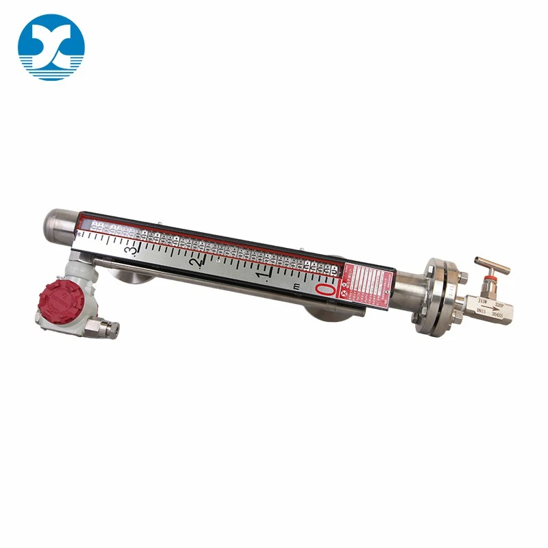
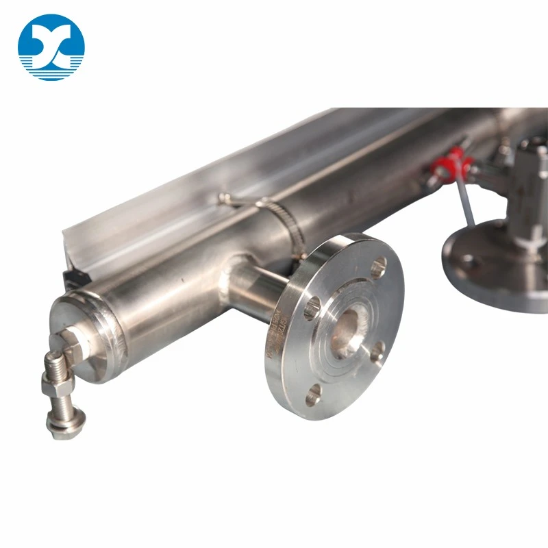
Why Choose Magnetic Level Gauge for Oil & Gas
Generic magnetic level gauges are seldom engineered for the specific demands of oilfield operation. Deployed on crude storage tanks, heavy-oil buffer vessels or hydrocarbon separators, they encounter two recurring failure modes: viscous crude gradually coats the float and chamber wall until motion becomes erratic or ceases, and paraffin wax drops out of solution as temperature falls, eventually constricting the measuring bore. Additionally, standard electronic add-on modules lack the explosion-proof documentation that oil & gas operators must produce during regulatory safety audits.
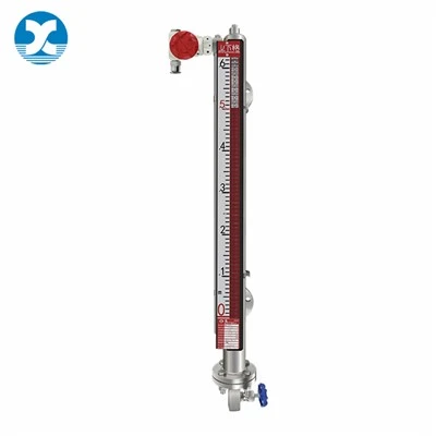
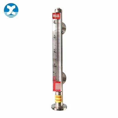
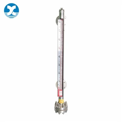
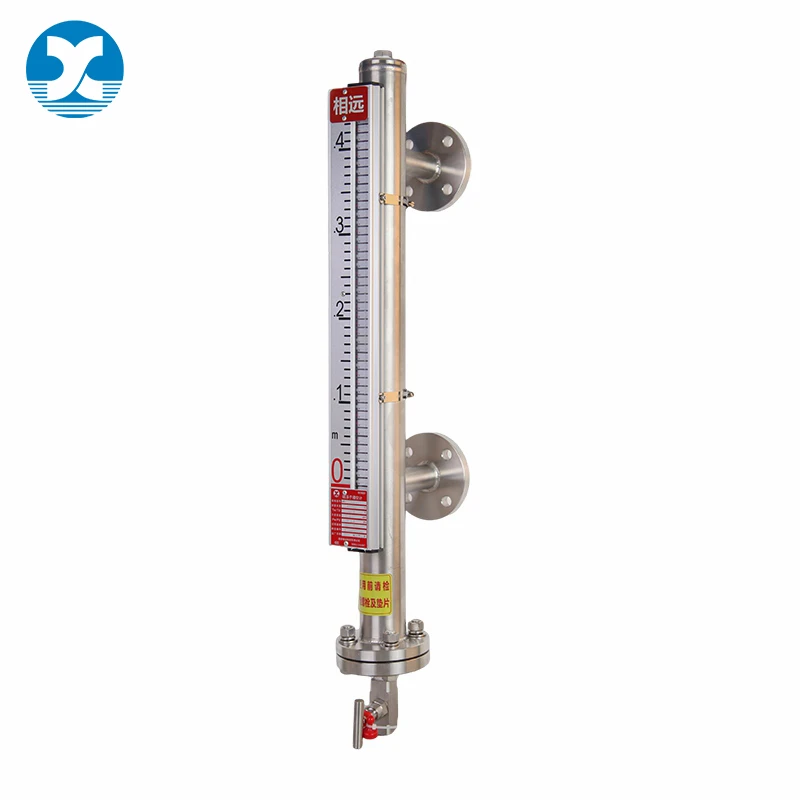
This dedicated oil & gas magnetic level gauge is constructed to eliminate those failure modes. The chamber interior receives a mirror-polish finish and the float is given a low-adhesion surface treatment, allowing crude and heavy oil to drain freely rather than cling. A steam-purge connection can be provided at the chamber base for periodic hot-oil or steam flushing that dissolves wax deposits before they cause obstruction. For hazardous-area installations, matched flameproof (Ex db) and intrinsically safe (Ex ia) transmitter and switch modules are available, ensuring conformity with Zone 1 and Zone 2 classification requirements.
This unit occupies a distinct position within the product portfolio:
- The chemical-tank variant emphasizes exotic-alloy corrosion resistance and anti-crystallization geometry for acids, alkalis and solvents. This oil & gas model instead prioritizes non-stick surfaces, wax-mitigation purging and explosion-proof module compatibility for hydrocarbon media.
- The LNG/LPG cryogenic variant incorporates a vacuum-insulation jacket and anti-frost baffle. This model carries no such insulation - it is intended for normal and medium-temperature crude, fuel oil and condensate service.
- Power-plant and water-treatment models target non-hazardous utility environments. This unit is oriented toward flammable hydrocarbon hazardous areas where explosion-proof certification is a non-negotiable procurement condition.
With full multi-signal expandability retained, the gauge performs equally well on onshore oil depots, well-site gathering skids and offshore platform auxiliary tanks, establishing it as the standard level-instrumentation selection for oil & gas storage and transportation systems.
Key Features and Benefits
-
Anti-Stick & Anti-Wax Mechanical Design
A mirror-polished chamber interior paired with a coated low-adhesion float substantially reduces crude oil, heavy oil and wax-oil adhesion, preventing float stagnation and seizure during extended oil storage operation. A blowdown connection is provided as standard; an optional steam-purge port supports routine oil-sludge evacuation and hot-steam flushing to inhibit paraffin precipitation from obstructing the measuring chamber.
-
Matched Explosion-Proof Electronic Modules
Flameproof and intrinsically safe transmitters together with magnetic switches can be supplied as a coordinated package, meeting oilfield explosion-protection norms and permitting safe installation in oil-tank zones and gas-gathering stations.
-
Wide Pressure & Multi-Signal Capability
The standard pressure envelope spans full vacuum to 16 MPa (Class 900); a 32 MPa ultra-high-pressure customized variant is obtainable, suiting both pressurized oil-gas separation vessels and atmospheric oil storage tanks. Bi-color magnetic flip delivers instant on-site indication; optional 4-20mA/HART transmitters enable remote centralized monitoring for oil-depot automation and SCADA integration.
-
Oil-Industry Standard Installation Interfaces
ANSI B16.5 oil-industry standard flanges are supported, in addition to welding and threaded connection alternatives, accommodating the complete range of global oil & gas tank nozzle standards.
Wax Prevention & Field Maintenance Guide for Oilfield Service
This section provides practical guidance specific to oil & gas operating environments, helping field teams maximize service life and measurement reliability on crude oil, heavy oil and condensate tanks.
Recommended Wax-Prevention Installation Practices
For waxy crude oil service, install the gauge with a slight downward tilt (3°–5°) at the lower connection to promote natural drainage of wax-laden oil back into the tank. Avoid horizontal chamber runs where wax can settle and solidify. Where ambient temperatures drop below wax appearance temperature, trace-heat tape can be fitted to the chamber exterior to maintain flowability.
Scheduled Cleaning & Purge Procedure
- Close both upper and lower isolation valves to isolate the gauge from the tank.
- Open the bottom drain valve to evacuate residual oil and loose wax deposits.
- Where a steam-purge port is fitted, inject low-pressure steam (≤0.3 MPa) for 5–10 minutes to dissolve hardened paraffin.
- Flush with clean diesel or hot water until discharge runs clear.
- Close drain valve, reopen isolation valves, and verify float movement by observing flap indicator response.
Maintenance Interval Reference
| Service Condition | Recommended Blowdown | Steam Purge | Full Inspection |
|---|---|---|---|
| Light crude / diesel | Every 6 months | As needed | Annually |
| Waxy crude / heavy oil | Every 3 months | Every 3 months | Every 6 months |
| Condensate / NGL | Every 6 months | Not required | Annually |
Explosion-Proof Zone Wiring Notes
When installing transmitter modules in Zone 1 or Zone 2 areas, ensure all cable glands are tightened to the manufacturer's torque specification and that intrinsically safe circuits are separated from non-safe circuits by at least 50 mm in the junction box. Cable entries must use certified explosion-proof glands matching the cable outer diameter.
Technical Specifications
Technical parameters below reflect standard oil & gas configuration. Custom high-pressure (32 MPa) and steam-purge variants are available on request.
| Parameter | Specification |
|---|---|
| Chamber Outer Diameter | 51, 55, 57, 60.3, 65, 76 mm; wall thickness tailored to pressure & temperature |
| Chamber & Flange Wetted Material | 304SS, 316L, Titanium, Hastelloy C276, Inconel 625, 310S |
| Float Material | 304SS, 316L, Titanium, Hastelloy C276, Inconel 625, 310S |
| Indicator Flap Temperature Resistance | Aluminum nylon flap: ≤150℃; All-metal flap: ≤400℃ |
| Working Pressure | Vacuum ~ 16 MPa (Class 900); Max bespoke design pressure: 32 MPa @100℃ |
| Medium Operating Temperature | -40℃ ~ 400℃ |
| Minimum Medium Density | ≥0.4 g/cm³ (subject to working pressure) |
| Medium Viscosity | ≤ 10⁻⁴ ㎡/s |
| Measuring Range | 200 mm ~ 5500 mm; standard tube length 6000 mm, extended range bespoke |
| Installation Mode | Flange, welding, thread connection bespoke (ANSI oil-standard flange optional) |
| Drain Port | Standard 1/2" internal thread drain valve, steam purge port bespoke |
| Vent Port | Not fitted as standard, configurable to customer requirement |
| Optional Supporting Accessories | Explosion-proof magnetic transmitter, magnetostrictive transmitter, differential pressure transmitter, passive magnetic switches |
Applications
-
Onshore Oil Depot Storage
Crude oil, diesel and refined-product storage tanks at onshore terminal and depot installations, where wax-mitigation performance and explosion-proof conformity are standard procurement prerequisites.
-
Well-Site Gathering & Separation
Oil-well gathering skids, three-phase separators and oil-gas separation vessels on production well pads, demanding compact footprint and dependable operation under variable pressure.
-
Offshore Platform Auxiliary Tanks
Auxiliary oil storage, slop tanks and process buffer vessels on offshore platforms, where real estate is limited and explosion-proof certification is obligatory.
-
Petrochemical Fuel-Oil Buffers
Fuel-oil and feedstock buffer tanks within petrochemical plant battery limits, integrating with plant DCS for uninterrupted inventory surveillance.
-
Natural Gas Condensate Recovery
Condensate recovery tanks and stabilizer-column bottoms in natural-gas processing facilities, handling light hydrocarbon liquids with elevated vapor pressure.
FAQ
Q1: What distinguishes the oil & gas model from the chemical-tank magnetic level gauge?
The oil & gas variant concentrates on anti-viscous-oil adhesion, paraffin-wax removal and explosion-proof module coordination for hydrocarbon media. The chemical-tank variant is constructed for acid, alkali and solvent corrosion resistance together with anti-crystallization geometry. Their material emphases, surface treatments and optional accessories are intentionally divergent.
Q2: Is this gauge appropriate for waxy crude oil tanks?
Affirmative. The polished chamber wall and anti-stick float curtail wax accumulation, and optional purge connections permit routine hot-steam or hot-oil flushing to dissolve deposited paraffin before it restricts float travel.
Q3: Is explosion-proof certification obtainable for Zone 1 oil-tank installations?
Both flameproof (Ex db) and intrinsically safe (Ex ia) transmitter and switch configurations are supported to satisfy Zone 1 and Zone 2 hazardous-area prerequisites. Certificates accompany the quotation.
Q4: Can it connect to an oil-depot DCS or SCADA network?
Furnished with 4-20mA / HART output transmitters, the gauge interfaces directly with conventional oil-depot automation and SCADA platforms for remote level observation and alarm interlock.
Q5: How is wax-related measurement degradation identified?
Typical indicators include sluggish or irregular flap motion, readings that trail actual tank level variations, and a gauge that indicates empty following a fill operation. Should these symptoms present, execute the blowdown and steam-purge routine detailed in the Wax Prevention & Field Maintenance Guide section.
Provide your medium classification (crude oil / diesel / condensate / heavy oil), operating temperature, hazardous-area zone designation and flange standard. Our oil & gas instrumentation engineers will compile a coordinated explosion-proof configuration proposal at no cost, with quotation dispatched within 24working hours. Click the contact button to submit your specifications.
Hot Tags: magnetic level gauge for oil & gas | explosion-proof anti-wax level indicator, China magnetic level gauge for oil & gas | explosion-proof anti-wax level indicator manufacturers, suppliers, factory, non contact level measurement, Side Mounted Lining PTFE Magnetic Level Gauge, Side Mounted PVDF Magnetic Level Gauge, Top Mounted PVDF Magnetic Level Gauge, Top Mounted Stainless Steel Magnetic Level Gauge, ultrasonic level transducers