Introduction
Magnetic level gauges are everywhere on process tanks. Operators rely on them for clear, instant local level sight, but automation teams often hit snags when pulling that same level data back to a PLC, DCS or SCADA system. Most off-the-shelf magnetic level gauges only carry visual indication. A large share ship with nothing more than 4–20 mA analog or simple reed switch alarm outputs, which means you need to plan your digital connection path before wiring starts.
Modbus and Profibus dominate fieldbus installations for this kind of tank instrumentation. Modbus is simple, affordable and easy to roll out for retrofits or compact skids. Profibus, especially Profibus DP, is widely seen across European continuous-process plants where consistent, predictable bus timing matters. This post walks through your available integration routes, hardware picks, configuration workflows and the common headaches that pop up during commissioning. We'll cover built-in digital transmitters, gateway conversions, wiring best practices, register mapping and how to match your setup to the control architecture you already have in place.
First: Check What Your Magnetic Level Gauge Actually Supports
Native digital transmitter vs separate protocol converter A basic magnetic level gauge has a float and sight chamber, and that's it. It shows level locally, with no native digital output. If you need bus communication, you've got two practical ways forward.
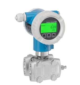
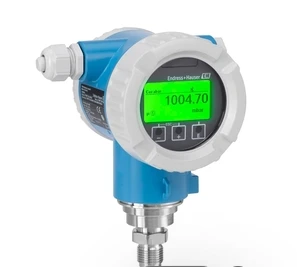
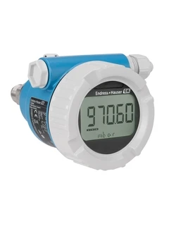
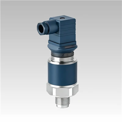
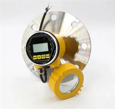
The cleaner approach is ordering the gauge pre-fitted with an integrated remote transmitter module. This mounts directly to the gauge chamber, tracks float position, and can be factory-configured for Modbus RTU, Modbus TCP, or Profibus PA/DP on request. This cuts down wiring and reduces extra hardware points that can fail.
The second method uses a standalone converter or gateway. This is your go-to when you already have gauges installed that only output a 4–20 mA analog signal. You feed that analog signal into a protocol gateway, which translates it into Modbus or Profibus telegrams for your control system. This retrofit path works well for brownfield sites, but it adds another device you'll need to calibrate, validate and maintain over time.
Know the difference between Modbus RTU, Modbus TCP, Profibus DP and Profibus PA Modbus RTU runs over shielded RS-485 twisted pair. It uses a master-slave polling model, and nearly every mid-range PLC and HMI supports it out of the box. It fits tank farms, small batch skids and scattered remote tanks nicely, though cable length and bus load need careful planning. Modbus TCP uses the same Modbus register structure over Ethernet, which makes sense when an industrial Ethernet backbone already sits close to your tank area.
Profibus splits into two common variants for process work. Profibus DP handles fast communication with PLC I/O and field devices, typical for production lines and packaged process equipment. Profibus PA is built for hazardous process zones, with bus-powered intrinsically safe operation. A Profibus PA-enabled magnetic level gauge can share the same fieldbus segment alongside other process transmitters, a major benefit inside classified explosion areas.
Don't mix these up casually. A Profibus DP master will not talk directly to a Modbus RTU slave, and vice versa, unless you add a gateway translation layer.
Integration Path 1: Modbus Setup for Magnetic Level Gauges
Hardware and wiring for Modbus RTU If your transmitter supports Modbus RTU, run shielded RS-485 twisted pair. Double-check A and B signal polarity - flipped A/B lines are one of the top reasons commissioning stalls. Fit 120-ohm termination resistors only at the two physical endpoints of the bus trunk, not on every single device. Extra terminators drag down bus voltage and create random, intermittent dropouts that are a nightmare to replicate during testing.
Route Modbus cables away from VFD wiring, high-current motor feeds and welding circuits whenever possible. Ground potential differences between the tank bonding point and control room ground also cause weird, unpredictable read errors. Galvanic isolation on the transmitter or gateway side often fixes this without tearing out and reworking the whole site grounding scheme.
Modbus configuration and register mapping Set the slave address, baud rate, parity and stop bits to match your Modbus master. Every vendor lays out registers differently, so grab the transmitter manual before building your PLC tag list. Most magnetic level transmitters put the primary level reading into one or two holding registers. Many also send supplementary data: tank temperature, diagnostic status, float fault flags and saturation alarms.
Stick with function code 03 for reading holding registers in most cases. Scale the raw integer value inside your PLC or HMI. The transmitter returns either a 16-bit or 32-bit raw count, and you apply scaling logic to convert that raw number into millimetres, metres or tank fill percentage. Avoid locking scaling inside the gateway unless your site standards demand it; keeping scaling inside the PLC makes future transmitter swaps far simpler.
Modbus TCP notes for cabinet-mounted networks Modbus TCP removes the RS-485 limits on node count and cable distance, but you still need solid industrial network hygiene. Assign static IPs to transmitters and gateways, document your subnet routing, and use managed switches with process VLAN segregation. Keep scan rates reasonable. Tank level changes slowly, so a 500 ms to one-second poll interval is more than sufficient. Faster polling just piles on unnecessary network traffic with zero improvement to your measurement.
Integration Path 2: Profibus Integration for Magnetic Level Gauges
Native Profibus PA or DP transmitters When your magnetic level gauge transmitter ships with native Profibus support, the supplier will provide a GSD file. This file defines device identity, available process data objects, diagnostic channels and the DP or PA profiles it supports. Import the GSD into your PLC engineering tool - TIA Portal or SIMATIC Manager, for example - before trying to map hardware.
Profibus PA devices connect to an intrinsically safe PA segment via a PA coupler. That coupler bridges the PA bus back to a Profibus DP master. This is the standard layout for chemical and oil & gas tank farms inside hazardous zones. If you select a Profibus DP transmitter instead, it connects straight to the DP trunk using standard Profibus RS-485 cable.
Gateway-based Profibus integration for Modbus-only transmitters Lots of magnetic level transmitters only offer Modbus RTU. If your plant runs a Profibus DP control network, add a Modbus RTU to Profibus DP gateway. On the Modbus side, the gateway acts as master, polling the level gauge. On the Profibus side, it appears as a regular DP slave to your PLC.
Data mapping inside the gateway is where most integrators cut corners. You define exactly which Modbus registers from the level gauge feed into which Profibus input bytes in the gateway's I/O block. Mess up byte or register ordering here, and your PLC will spit out garbage floating-point values even when the bus status light looks healthy. Always validate readings with a bus monitor tool before handover.
Profibus wiring and termination rules Use the correct purple Profibus cable for DP segments. Flip on the built-in termination switch only at both ends of each bus segment. Keep stubs short; long tap lines introduce signal reflection. Bond cable shield properly at the control room end, following your site's equipotential bonding plan. Poor shielding and floating potentials create those classic intermittent bus faults that eat hours of troubleshooting time.

Step-by-Step Commissioning Workflow Bench-test whenever you can.
Power the transmitter independently, connect a laptop with vendor configuration software or a Modbus polling tool, and confirm stable level readings before mounting it on the tank. This catches bad addresses, mismatched baud settings or DOA hardware before you climb the tank or pull new cable trays.
Once physically installed, lock in all bus parameters: slave address, baud, parity, Profibus station number and watchdog timeouts. Load the GSD file for Profibus hardware and compile your hardware configuration. Download to the PLC and keep an eye on bus diagnostic counters. Watch for retries, frame errors or dropped slaves before enabling automatic pump or valve control logic.
Calibrate the level span against your tank geometry. Even with fully digital transmission, a sloppy calibration will give wrong operator displays and bad control actions.
Finally, bring diagnostic tags into your SCADA alarm stack. Instrument fault, float-stuck flags and bus watchdog status all deserve alarm points. A magnetic level gauge can lose tracking if the float seizes up, and the bus will happily keep returning the last valid reading unless the transmitter sends a fault bit.
Common Integration Pitfalls to Avoid
- First,Don't assume every magnetic level gauge has digital output. Standard units only give local sight and reed switch alarm points. You have to specify the digital transmitter option at order time, or budget for a converter later.
- Second, watch bus loading. RS-485 Modbus segments have hard limits on node count and cable length, and those limits shrink at higher baud rates. Overloading a trunk with too many transmitters, flow meters and temperature probes creates unstable communication.
- Third, byte and word ordering breaks floating-point register reads constantly. Vendors mix big-endian and little-endian register packing. If your value jumps around randomly or reads as a nonsensical negative number, test byte swapping first before replacing hardware.
- Fourth, don't overlook hazardous-area compliance. If the tank sits inside an Ex zone, your transmitter, gateway, cabling and power supply all need matching approvals. A generic RS-485 gateway without suitable certification cannot live inside the classified area.
How to Choose Between Modbus and Profibus for Your Project
Pick Modbus RTU or Modbus TCP for retrofits, small tank farms, water treatment skids or cost-sensitive builds. It costs less, works with nearly every toolset, and most system integrators can troubleshoot it quickly.
Go with Profibus when your site's existing DCS or PLC standard is Profibus DP/PA, you need PA intrinsic safety for classified process areas, or the end user requires deterministic bus timing for continuous process control. Profibus hardware and engineering usually run pricier, but it slots neatly into established European process plant architectures.
If you run a mixed system, gateway conversion works, but clearly mark that translation point on your electrical drawings. Every gateway becomes a single point of failure, so talk through redundancy requirements with the end user for safety-critical tanks.
Closing Thoughts
Magnetic level gauges deliver rock-solid local visual indication, and they integrate smoothly into digital control systems if you map the connection path upfront. The core decision is whether you specify a native digital transmitter when ordering, or add a gateway later for existing retrofits. Modbus is the flexible, widely supported default. Profibus shines for sites already running that fieldbus standard, especially inside hazardous process zones.
Take time for bench testing, follow wiring and termination rules closely, document register mapping, and pull diagnostic fault bits into your control system. That small extra care keeps simple bus issues from snowballing into unplanned tank-level downtime. When specifying a new gauge, share your PLC protocol standard with the supplier early. That way, the unit ships pre-configured and ready to drop straight onto your bus network.
References
- IEC 61158, Digital data communications for measurement and control – Fieldbus for use in industrial control systems (Profibus standard)
- Modbus Organization, Modbus Application Protocol Specification V1.1b3
- IEC 61326-1, Electrical equipment for measurement, control and laboratory use – EMC requirements
- PROFIBUS International, PROFIBUS PA Installation and Commissioning Guideline
- ISA-50.02, Fieldbus Standard for Measurement and Control