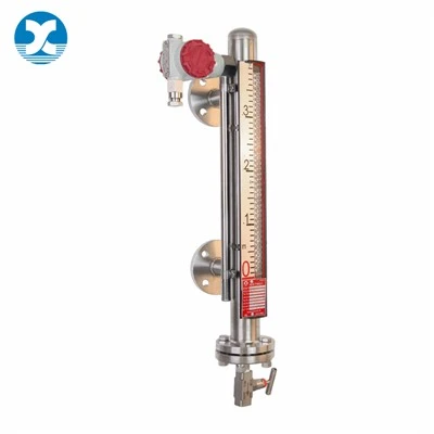
Ultrasonic level transmitters have become a go-to budget non-contact option for clean water tanks and open-channel flow systems. No wetted probes, simple top-mount installation, and low upfront pricing make them appealing for straightforward low-complexity projects.
But field experience shows this technology hits hard limits once process conditions move beyond clean, ambient-temperature water. Countless site teams run into erratic readings, signal dropout, and constant calibration drift after installation, simply because they underestimated how many common industrial factors disrupt acoustic wave operation. I've seen projects delay startup, reorder replacement instruments, and accept persistent inventory errors all because the team didn't map out ultrasonic's core constraints before specifying the gauge.
This guide breaks down every key limitation of ultrasonic level gauges encountered in daily plant operation, explains the physics behind each restriction, lists application scenarios where they fail entirely, and offers proven alternative measurement technologies for each pain point. All observations align with standard ISA and OEM instrument operating guidelines, with actionable selection tips to avoid costly mis-specification.
Core Working Principle Context (To Understand Its Limitations)
Before diving into drawbacks, a quick recap of how ultrasonic level gauges operate, as every limitation traces back to this basic acoustic design.
The top-mounted transducer emits high-frequency sound pulses that travel through air inside the tank headspace. The pulse bounces off the liquid or solid surface, and the sensor calculates distance based on the time taken for the echo to return - called time-of-flight (ToF) measurement.
Critical detail: Sound waves rely on a gaseous medium (air) to propagate. Any change to that air layer, or any surface that absorbs/scatters sound energy, directly breaks reliable measurement. Unlike radar microwaves or buoyancy-based magnetic gauges, acoustic signals cannot bypass vapor, foam, dust or vacuum environments without severe signal loss. This single physical constraint creates nearly all the field limitations covered below.

Primary Limitations of Ultrasonic Level Gauges
1. Signal Failure Under Foam, Vapor, Steam & Turbulent Surfaces
This is the most frequent complaint logged for ultrasonic level instruments across chemical, food processing and wastewater facilities. Thick foam layers on liquid surfaces absorb almost all acoustic energy, with almost no usable echo bouncing back to the transducer. Even thin aerated foam scatters sound pulses randomly, leading to jumping, untrustworthy readings that swing wildly during filling or draining cycles.
Heavy vapor, solvent fumes or steam fill the tank headspace with mixed gas layers of varying density. These layers refract sound waves, altering pulse travel speed and sending false echo signals back to the sensor. For hot process tanks with continuous steam output, ultrasonic gauges will drift dozens of millimeters or lose full signal within hours of startup.
High turbulence from agitators, incoming feed streams or recirculation pumps creates uneven surface waves that disperse sound pulses. The sensor cannot lock onto a consistent surface reference, triggering constant false high/low level alarms that force operators to disable level interlocks entirely.
2. Severe Sensitivity to Temperature Shifts & Thermal Gradients
The speed of sound through air changes linearly with air temperature, following a well-documented industry formula: sound velocity = 331.4 + 0.6 × ambient temperature (°C). Even modern ultrasonic transmitters with built-in temperature compensation only correct for uniform, slow temperature changes.
Rapid thermal swings or vertical thermal gradients inside a tank break this compensation logic. A 30°C temperature shift in the headspace can create 1% to 2% full-range measurement error, enough to throw off batch dosing and inventory tracking on medium and large storage vessels.
Extreme high temperatures present a second risk: sustained heat above 80°C damages the piezoelectric ceramic element inside the transducer, permanently degrading its ability to generate and receive sound pulses. For hot process media above 100°C, ultrasonic hardware has no viable long-term service life.
3. Zero Functionality in Vacuum & Low-Pressure Environments
Sound waves cannot travel without air molecules to carry mechanical vibration. In high-vacuum reactors or low-pressure sealed vessels, the thin gas atmosphere drastically attenuates acoustic pulses, resulting in zero return echo and complete measurement failure.
Even mild negative pressure (partial vacuum) creates consistent large reading offsets that temperature compensation cannot resolve. Any process operating below standard atmospheric pressure eliminates ultrasonic as a viable measurement option entirely - a hard limitation not present in radar, DP or magnetic level gauge designs.
4. Inherent Dead Band (Blind Zone) Near the Transducer
Every ultrasonic level gauge has a fixed dead band directly beneath the transducer face, a minimum distance where the sensor cannot distinguish the outgoing pulse from the returning echo. Dead band width scales with the instrument's maximum measuring range: longer-range units have larger blind zones, often 300–500 mm minimum clearance below the sensor.
This creates two practical operational headaches:
- Tanks with shallow total liquid depth cannot use ultrasonic gauges, as the normal operating level will regularly enter the blind zone and produce no valid reading.
- Designers must mount the transducer far higher above the tank's maximum fill level, reducing usable measuring range and limiting the gauge's effective span.
No software adjustment can eliminate this physical blind zone; it is a permanent hardware limitation of time-of-flight acoustic technology.
5. Dust, Condensation & Contamination Block Signal Transmission
Dust clouds in bulk solid silos or powder processing tanks scatter sound pulses, weakening echo strength to unreadable levels. Even moderate dust buildup on the transducer face dampens pulse vibration, gradually reducing signal consistency over weeks of operation.
Condensation, water droplets or process residue coating the transducer diaphragm act as a sound dampener. Outdoor tanks, cooling towers and humid chemical storage vessels regularly develop thin water films on the sensor that cut echo return strength in half. While low-frequency ultrasonic models offer minor self-cleaning vibration, they cannot eliminate persistent heavy buildup.
6. False Echoes From Internal Tank Obstacles
Any rigid structure inside the sound wave path generates competing false echoes that confuse the sensor's signal processing algorithm. Common interfering obstructions include agitator blades, support ladders, internal piping, baffles and tank wall protrusions.
Even with advanced echo suppression software, complex tank internals create intermittent false high-level readings that trigger safety interlocks unnecessarily. Operators often disable critical high-level overflow protection to stop constant false alarms, introducing major process safety risks.
7. Limited Pressure Operating Envelope
Ultrasonic transmitters are engineered for near-atmospheric open or low-sealed tank service. Elevated internal tank pressure changes air density, altering sound wave propagation speed and creating uncorrectable measurement drift. Most standard ultrasonic models cannot reliably operate above 3 bar internal pressure, ruling them out for pressurized process reactors, boiler feed tanks and compressed gas storage vessels.
8. Susceptible to Acoustic & Electromagnetic Interference
Loud industrial background noise from pumps, compressors, grinding equipment and agitators generates competing sound waves that mask the liquid surface echo. On busy production floors, ultrasonic readings become unstable and untrustworthy during peak machine operation.
Nearby high-frequency VFD drives, large transformers and motor control panels create electromagnetic interference that corrupts the transmitter's signal circuit, leading to random reading jumps and loss of 4–20mA output communication. Shielded cable installation mitigates this but adds extra engineering and material costs that erase ultrasonic's budget advantage.
Where Ultrasonic Level Gauges Should Not Be Specified
Based on aggregated field troubleshooting records, these application categories consistently lead to poor ultrasonic performance and should use alternative instruments instead:
- Tanks with thick foam, heavy steam, aerated liquids or turbulent agitated media
- Vacuum reactors, low-pressure sealed vessels and high-pressure process tanks
- Hot process media with sustained headspace temperatures exceeding 80°C
- Powder silos, dust-heavy bulk solid storage and high-humidity condensation-prone tanks
- Shallow small vessels where liquid level regularly enters the transducer dead band
- Complex internal tank geometry with agitators, ladders and internal piping
- Batch processes with rapid, wide temperature swings inside the tank headspace
Suitable Alternatives for Each Limitation
|
Pain Point |
Recommended Replacement Technology |
Key Advantage Over Ultrasonic |
|
Foam, vapor, steam, dust |
80 GHz non-contact radar level gauge |
Microwaves pass through foam, vapor and dust without signal attenuation; unaffected by air density shifts |
|
Vacuum / high pressure vessels |
Magnetic side-mounted level gauge / DP transmitter |
No air-dependent measurement medium; fully sealed pressure-rated chamber |
|
High temperature process tanks |
Guided wave radar or PTFE lined magnetic level gauge |
Wide temperature operating range, no heat-sensitive transducer elements |
|
Shallow small tanks with limited clearance |
Compact guided wave radar (minimal dead band) |
Blind zone under 50 mm, no large mounting overhead space required |
|
Complex tank internals with agitators |
Side-mounted magnetic flapper level gauge |
Bypass chamber isolates measurement from all internal tank obstructions |
Narrow Scenarios Where Ultrasonic Level Gauges Still Perform Well
Ultrasonic technology is not universally bad - it delivers stable, cost-effective readings only under tightly controlled clean conditions:
- Open-channel clean water flow measurement with weirs/flumes
- Atmospheric clean water storage tanks with no foam, vapor or dust
- Remote solar-powered underground sewage basins with consistent ambient temperature
- Low-budget, low-risk non-critical buffer tanks with minimal temperature fluctuation
- Outdoor rainwater collection vessels with clear, calm liquid surfaces
When all these conditions align, ultrasonic's low material cost and simple top-mount installation make it a reasonable selection. The critical error most specification engineers make is stretching ultrasonic beyond this narrow operating window.
Frequently Asked Questions
Can temperature compensation fully eliminate ultrasonic reading drift?
Standard built-in temperature compensation only accounts for slow, uniform air temperature changes. Rapid thermal gradients, vertical hot/cold air layers or extreme sustained heat will still create measurable offset errors that software cannot fully correct.
Is dead band avoidable with high-frequency ultrasonic sensors?
Higher-frequency units shrink dead band slightly but cannot eliminate it entirely. Any ultrasonic ToF sensor requires a minimum separation distance to distinguish outgoing and returning sound pulses, leaving a permanent blind zone beneath the transducer.
Can ultrasonic gauges read through foam or heavy vapor?
No. Foam absorbs acoustic energy, while vapor layers refract sound waves. No firmware or transducer upgrade can recover a usable echo signal under these conditions; radar or magnetic level instruments are the only reliable substitutes.
Do ultrasonic level gauges work in vacuum tanks?
They cannot. Sound waves require gaseous air molecules to propagate. Vacuum environments remove this transmission medium, resulting in zero echo return and complete measurement failure.
How much maintenance do ultrasonic transmitters require compared to magnetic level gauges?
Ultrasonic units need regular transducer face cleaning to remove condensation, dust and residue to maintain signal strength. Magnetic bypass gauges have no exposed sensing elements and only require quarterly chamber flushing, with far less frequent upkeep over full service life.
Final Selection Takeaways
Ultrasonic level gauges fill a specific niche for low-complexity, clean ambient water applications, but their acoustic operating principle creates hard physical limitations that cannot be engineered away with software upgrades or minor accessory adjustments. Every project team weighing ultrasonic hardware must first audit tank conditions for foam, vapor, temperature swings, pressure rating and internal obstructions before finalizing specifications.
Mis-specifying ultrasonic for harsh process media creates avoidable costs: rework labor, replacement instrument lead times, unplanned downtime and safety risks from unreliable level interlocks. When process conditions fall outside ultrasonic's narrow operating window, radar, differential pressure or magnetic level gauges deliver consistent long-term readings with fewer maintenance headaches.
If you are comparing level measurement technologies for your tank application and need help identifying whether ultrasonic is viable, or want sizing recommendations for radar/magnetic gauge alternatives, share your process temperature, pressure, medium properties and tank geometry with our technical team for a tailored selection review.
References
- International Society of Automation (ISA). (2025). Basics of Continuous Industrial Level Measurement. Research Triangle Park, NC: ISA.
- Endress+Hauser. (2024). Ultrasonic vs Radar Level Measurement Technical Whitepaper. Endress+Hauser Measurement SolutionsEndress+Ha....
- American Petroleum Institute (API). (2022). Tank Level Measurement Selection Guidelines for Process Vessels. Washington, DC: API.
- Lamont Controls. (2025). Comparing Magnetic Level Gauges to Ultrasonic & Radar Instruments. Retrieved from https://www.lamontcontrols.com/technical-resources/comparing-magnetic-level-gauges-to-other-level-measurement-technologies.
- Zero Instrument Technology. (2026). Field Troubleshooting Guide for Ultrasonic Level Transmitters. Retrieved from https://zeroinstrument.com/ultrasonic-level-sensor-fault-solutions.
- ASME B31.3-2023. Process Piping Standard, Level Instrument Installation Section. American Society of Mechanical Engineers.