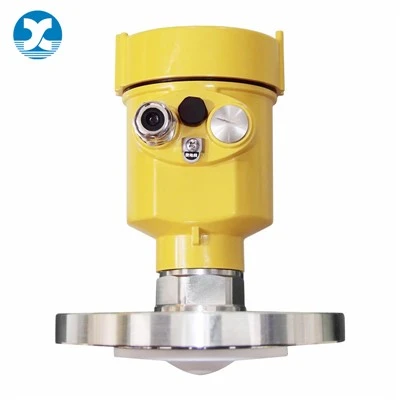
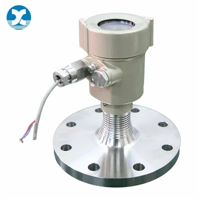
The monocrystalline silicon pressure transmitter is a pressure sensor based on a monocrystalline silicon chip, manufactured using German MEMS technology and an all-welded sensor module. It converts pressure changes into standardized electrical signals such as 4-20mA HART through the piezoresistive effect, and is widely used in petrochemical, pharmaceutical, and aerospace industries to measure the pressure, level, and density of liquids, gases, or vapors.
The core of this device is a monocrystalline silicon piezoresistive sensor, integrating temperature compensation and a dual overload protection diaphragm structure, providing electromagnetic interference resistance. Utilizing nano-monocrystalline silicon material and a high-purity double-beam suspension design, it achieves an accuracy of 0.075%FS, a maximum range ratio of 200:1, supports wide temperature range operation (-40~120℃), and IP66/IP67 protection rating. With a built-in HART protocol, it can be used for parameter setting and communication via HART375 and other devices, making it suitable for complex industrial environments such as explosion-proof and hygienic applications.
Working Principle
The sensor module employs all-welded technology and internally contains an integrated overload diaphragm, a pressure sensor, and a temperature sensor. The temperature sensor serves as a reference value for temperature compensation. The positive pressure side of the pressure sensor is connected to the high-pressure chamber of the sensor diaphragm housing, and the negative pressure side is connected to the low-pressure chamber. Pressure is transmitted through the isolation diaphragm and filling fluid to the silicon chip inside the sensor, causing a change in the resistance of the pressure sensor chip, thereby resulting in a change in the output voltage of the detection system. This output voltage is proportional to the pressure change and is then converted into a standardized signal output by the adapter unit and amplifier.
Working Principle of Monocrystalline Silicon Piezoresistive Pressure Sensor
The piezoresistive pressure sensor utilizes the piezoresistive effect of monocrystalline silicon. A monocrystalline silicon wafer is used as the elastic element. Using integrated circuit technology, a set of equivalent resistors is diffused in a specific direction on the monocrystalline silicon diaphragm and connected in a bridge circuit. The monocrystalline silicon wafer is placed inside the sensor cavity. When the pressure changes, the monocrystalline silicon undergoes strain, causing the strain resistors directly diffused on it to change proportionally to the measured pressure. The corresponding voltage output signal is then obtained by the bridge circuit.

The structure of a monocrystalline silicon pressure sensor: The main components are two process diaphragms, a silicon sensor in the middle, and filling oil and process connections.

Function
Monocrystalline silicon pressure/differential pressure transmitters are used to measure the level, density, and pressure of liquids, gases, or vapors, and then convert them into a 4-20mA HART current signal output. They can also communicate with HART375 or BST Modem for parameter setting and process control. The difference between them and traditional pressure transmitters is that they use nano-monocrystalline silicon as the sensor material.
Troubleshooting
Inspection of the Transmitter Measurement Section
1. Remove the flange and check the sensitive component's diaphragm for deformation, damage, or oil leakage.
2. Remove the compensation plate, without removing the sensitive component, and check the insulation resistance of the pins to the housing. Under voltage not exceeding 100V, the insulation resistance should not be less than 100MΩ.
Connect the circuit and air supply. When the pressure signal is at the upper limit of the range, turn off the air supply. The output voltage and reading should remain stable. If the output voltage drops, it indicates a leak in the transmitter. The leak can be located using soapy water.
Circuit Inspection
1. Connect the power supply and check the voltage signal status at the transmitter output terminal. If there is no output voltage, first check if the power supply voltage is normal and meets the power supply requirements; check for wiring errors between the power supply, transmitter, and load equipment. No voltage at the transmitter terminals or reversed polarity can cause no voltage signal output. After ruling out these causes, further check for damaged components in the amplifier board circuit; check for poor contact in the circuit board connectors. The fault point can be determined by comparing the measured voltage of a normal instrument with the corresponding measured voltage of the faulty instrument. If necessary, replace the faulty amplifier board. When inspecting flow-type transmitters, special attention should be paid to taking anti-static measures for J-type amplifier boards.
2. Connect the power supply. After giving an input pressure signal, if the transmitter output is too high (greater than 10VDC) or too low (less than 2.0VDC), and there is no response when changing the input pressure signal or adjusting the zero point and range screws, then the transmitter output is faulty. For this type of fault, in addition to checking for abnormalities in the sensitive components of the transmitter's measuring section, the "oscillation control circuit" on the transmitter amplifier board should be checked for proper operation. The normal peak voltage between the high-frequency transformers T1-12 should be 25~35VP-P; the frequency is approximately 32kHz. Next, check the operating status of each operational amplifier on the amplifier board; check for any damage to the components, etc. This type of fault requires replacement of the amplifier board.
On-site Troubleshooting
1. Primary components are blocked or incorrectly installed; pressure taps are not properly positioned.
2. Pressure tapping lines are leaking or blocked; residual gas or liquid remains in the charging line; deposits exist in the transmitter process flange, creating a measurement dead zone.
3. Transmitter wiring is incorrect; power supply voltage is too high or too low; poor contact at the connection between the indicator and instrument terminals.
4. Insufficient installation according to technical requirements; installation method and site environment do not meet technical requirements.