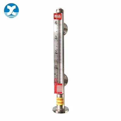
A transmitter converts parameters such as temperature, pressure, flow rate, liquid level, and composition into a 4-20mA current signal. As long as there are no branches in the transmission loop, the current in the loop will not change with the length of the wire, thus ensuring transmission accuracy.
Two-wire transmitter and wiring
The wiring diagram for a two-wire transmitter is shown in Figure 1. It is powered by 24VDC, outputs a 4-20mA signal, and the load resistance is typically 250Ω. The negative wire of the 24V power supply has the lowest potential; this is the common point. Intelligent transmitters can also load HART protocol FSK keying signals onto the 4-20mA signal. Some digital displays have transmission functions or 24V power supply capabilities, functioning similarly to two-wire transmitters.

The power supply and current signal loop for a two-wire transmitter is as follows: 24V power supply positive terminal → transmitter positive terminal → transmitter negative terminal → digital display positive terminal → digital display negative terminal → 24V power supply negative terminal. The digital display receives a current signal. If a resistor R is connected in parallel between the positive and negative terminals of the digital display, the digital display receives a voltage signal.
Three-wire transmitter and wiring
A three-wire transmitter uses one wire for the power supply positive terminal, one wire for the signal output positive terminal, and one wire shared between the power supply negative terminal and the signal negative terminal, as shown in Figure 2. The power supply is mostly 24VDC, and the output signal is mostly 4-20mA.

The power supply circuit for a three-wire transmitter is: 24V positive terminal → transmitter positive power supply terminal V+ → transmitter negative terminal (common terminal) → 24V negative terminal. The current signal circuit is: transmitter current output terminal I+ → digital display positive terminal → digital display negative terminal → transmitter negative terminal (common terminal). The digital display receives the current signal. If a resistor R is connected in parallel between the positive and negative terminals of the digital display, the digital display receives a voltage signal.
Four-wire transmitters and wiring
Four-wire transmitters use two wires each for power and signal, operating separately. As shown in Figure 3, the power supply is mostly 220VAC, but 24VDC is also possible. The output signal is mostly 4-20mA. The current signal circuit for a four-wire transmitter is: transmitter current output positive terminal → digital display positive terminal → digital display negative terminal → transmitter negative terminal. The digital display receives the current signal. If a resistor R is connected in parallel with the positive and negative terminals of a digital display, the digital display will receive a voltage signal.