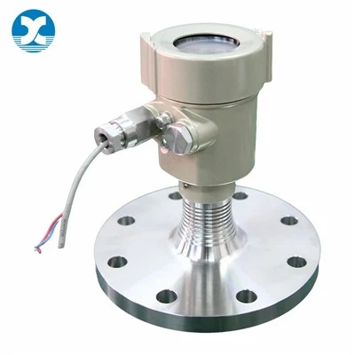
Temperature transmitters act as the critical bridge between raw temperature sensors and plant control systems. They take weak signals from RTDs or thermocouples and convert them into clean, noise-immune outputs for PLC, DCS and SCADA hardware. Even with high-grade PT100 or thermocouple probes fitted on site, picking an ill-suited transmitter will bring measurement drift, unstable loop behaviour and unplanned production downtime.
Many buyers make quick decisions driven largely by unit price or basic input-output specs. They overlook mounting style, site environmental limits, loop load constraints and protocol fit. Small specification oversights often only surface after commissioning, forcing costly rework on live production lines. This guide breaks down practical selection criteria, includes an anonymized real-plant case, calls out frequent field missteps and delivers a usable pre-purchase checklist. All content aligns with established industry standards and real-world commissioning experience.
What an Industrial Temperature Transmitter Actually Does
A PT100 outputs subtle resistance changes. A thermocouple generates tiny millivolt signals. Neither travels well over long field cables, especially in areas close to variable-frequency drives and heavy-duty motors.
Temperature transmitters receive these fragile sensor inputs, run signal conditioning, cold-junction compensation, range scaling and basic fault detection, then deliver standardized outputs. Two-wire 4-20 mA loop-powered output remains the industry standard. Smart variants add HART or Modbus RTU to support remote configuration and on-board diagnostics.
Three common form factors dominate installations: head-mount units that sit inside standard sensor connection heads, DIN-rail modules housed inside control cabinets, and fully integrated units pre-assembled onto temperature probes. Your choice of hardware form directly impacts installation labour, maintenance effort and long-term measurement reliability.

Core Practical Selection Criteria
Sensor Input Compatibility
Start by validating transmitter input matches your existing or planned sensor hardware.
- RTD input (PT100 is most common): Confirm support for 2-wire, 3-wire or 4-wire RTD configurations. Three-wire is standard for most industrial sites to offset cable resistance errors. Two-wire RTD creates noticeable lead-resistance drift for longer cable runs.
- Thermocouple input: Double-check exact thermocouple type (K, J, T, S, B and so on). Cold-junction compensation performance deserves close attention. Low-cost transmitters with poor-grade CJC will produce steady measurement offset whenever head or cabinet ambient temperature shifts.
Some universal-input transmitters accept both RTD and thermocouple types. These are handy for mixed-sensor retrofit projects. Still, review accuracy datasheets carefully; multi-purpose universal hardware sometimes sacrifices per-channel measurement performance.
Output Signal and Communication Protocol
Align output options with your control hardware and site maintenance workflow.
- 4-20 mA two-wire loop powered: The industry workhorse. Good noise rejection, supports long cable distances, compatible with nearly all PLC and DCS analog input cards. Respect published loop supply voltage and maximum loop resistance limits; ignoring these will cause signal saturation under real-world load.
- HART protocol: Overlays digital diagnostic data onto existing 4-20 mA analog loops. Operators can set measuring ranges, adjust damping values, read device status and flag sensor open-circuit faults without opening field enclosures. This adds real value for hard-to-access measuring points or hazardous-area installations.
- Modbus RTU: Pure digital bus solution, best for dense multi-point monitoring setups. Requires matching master hardware, and is not a practical fit for legacy analog-based control systems.
- 0-10 V voltage output: Only suitable for short cable distances, rarely deployed for field-mounted process transmitters.
Avoid over-specifying features you will never use. If your site has no HART communicators on hand, sticking with basic 4-20 mA hardware keeps costs in check with zero performance downside.
Accuracy, Drift and Measuring Range
Evaluate total system error instead of only reading standalone transmitter accuracy figures. General industrial transmitters deliver ±0.1 %FS to ±0.5 %FS accuracy. Precision-critical reactors or quality-related monitoring points require total error ≤±0.1 %FS; for thermocouple inputs, remember to factor in CJC error as part of this budget.
Long-term drift is easy to overlook. A transmitter with impressive initial accuracy but high annual drift will gradually shift readings month over month, forcing more frequent calibration work. For continuous-operation plants, prioritize units with clearly documented low long-term drift performance.
Set your measuring range as narrow as your real-process operating window allows. Retaining factory-set wide span unnecessarily amplifies absolute measurement error. Always rescale transmitters on-site to match actual working temperature limits.
Mechanical Form, Ingress Rating and Site Environmental Conditions
Transmitters operate in very different environments: climate-controlled cabinets, damp outdoor pipe racks, dusty production floors, explosive hazardous zones.
- Head-mount: Installed right inside sensor connection heads next to the probe. Minimizes raw sensor lead-wire length and cuts noise pickup. Widely used on tanks, pipelines and reactors. Keep an eye on ambient temperature limits for electronics; radiant heat from hot uninsulated pipes will degrade transmitter performance.
- DIN-rail mount: Fits inside control cabinets. Sensors run longer cables back to the control room. Proper shielding and cable management become critical in electrically noisy plant environments.
- Integrated probe-transmitter assembly: Compact and fast for standard-range applications, yet less flexible if you later need to swap out sensors.
Check enclosure IP ratings; IP65 or IP67 are typical for dust and moisture exposure. For hazardous locations, verify formal certification such as Ex ia intrinsically safe or Ex d flame-proof, matching your zone classification. Do not trust vague marketing claims like "explosion-resistant" without valid certification paperwork. Galvanic isolation is highly recommended when ground-potential differences exist between field sensors and control-room hardware, to prevent hidden measurement offsets.
Power Supply and Loop Load Constraints
Two-wire 4-20 mA transmitters draw operating power directly from the signal loop. Every model defines minimum supply voltage and maximum allowable loop resistance. Total loop resistance combines field cable resistance plus input impedance from your PLC or DCS module. Exceed published limits and the output cannot reach full 20 mA, bringing clipped readings and intermittent faults that often do not show up during bench testing.
Many field complaints labelled "faulty transmitter" actually trace back to insufficient loop voltage or excessive loop resistance.
Real-World Field Case: Poor Transmitter Specification Triggers Recurring Measurement Drift
A processing facility carried out temperature-measurement upgrades across multiple batch reaction vessels. The engineering team kept existing K-type thermocouple probes and ordered low-cost universal-input head-mount transmitters, with unit price as the main decision factor. Vessels ran between 60 °C and 220 °C, and production needed stable temperature control held within ±0.8 °C.
After commissioning, operators noticed slow, consistent measurement drift. Readings drifted several degrees over multiple days. Hand-held reference checks confirmed thermocouple probes themselves worked fine. Maintenance crews retightened terminals, swapped field cables and tweaked controller parameters, yet drift persisted.
Technical review uncovered two root causes. First, budget transmitters used basic cold-junction compensation. Connection heads saw large day-night ambient temperature swings, introducing variable CJC offset. Second, site ground-potential differences created ground-loop interference; the selected transmitters offered no galvanic isolation.
Instead of full system replacement, the facility upgraded to HART-capable head-mount transmitters with improved CJC accuracy and galvanic isolation. Existing thermocouple probes and field wiring remained in service. After installation and correct range configuration, measurement drift disappeared. Batch-to-batch temperature consistency improved, and repeated on-site trimming work was eliminated. This case illustrates that transmitter internal specs, not just sensor quality, dominate real-world measurement performance.
Common Selection and Installation Mistakes to Avoid
Ignoring CJC performance for thermocouple inputs
For thermocouple setups, cold-junction compensation error adds directly to total system error. Many buyers only look at quoted transmitter accuracy and skip checking CJC specs. Under shifting ambient temperatures, low-grade CJC produces noticeable offset that controller trimming cannot fully fix.
Keeping unnecessarily wide factory measurement ranges
Using factory full-span ranges when your process only uses a narrow temperature band inflates absolute measurement error. Always rescale transmitters to match real operating span.
Neglecting loop resistance and power budget
Two-wire 4-20 mA transmitters have strict loop limits. Long, thin cables add considerable resistance. Always calculate total loop resistance against datasheet limits before deployment.
Wrong form factor for high-radiant-heat locations
Head-mount transmitters fitted directly onto hot uninsulated thermowells run at elevated electronics temperature. This accelerates drift and shortens service life. Where radiant heat is significant, use remote DIN-rail transmitters or fit thermal isolation accessories for sensor heads.
Skipping galvanic isolation on multi-ground-point sites
If sensors and control cabinets connect to separate ground points, ground-loop currents flow through signal wiring. Without galvanic isolation you get wandering readings that puzzle maintenance teams.
Pre-Purchase Selection Checklist
Work through these points before locking in your order:
- Confirm sensor hardware: PT100 RTD (2/3/4-wire) or thermocouple type (K, J, T and others)
- Map actual process temperature span; set transmitter range matching real operating conditions
- Confirm output type: 4-20 mA, HART, Modbus RTU, verify compatibility with existing PLC / DCS
- Decide mounting style: head-mount, DIN-rail, integrated probe assembly
- Assess site conditions: ambient temperature range, moisture, dust, vibration; required IP rating
- Hazardous-area requirement: confirm whether explosion-protection certification is needed
- Check if galvanic isolation is required, especially for long cables or multi-ground-point installations
- Calculate total loop resistance and cross-reference against transmitter loop-power specifications
- Review on-site maintenance workflow: will technicians require remote HART configuration and diagnostics?
Frequently Asked Questions
Do I have to use a temperature transmitter, or can I wire RTD / thermocouple straight to PLC?
Some PLC modules accept native RTD or thermocouple inputs. Even so, transmitters deliver tangible benefits: signal conditioning, better noise immunity, fault detection and standard 4-20 mA signals for long cable runs. For remote field points or electrically noisy plant floors, transmitters are strongly recommended.
Are HART transmitters worth extra cost if we do not own a HART hand-communicator?
HART adds hardware cost. Without compatible HART tools you cannot leverage remote configuration or diagnostic features. In that scenario, standard 4-20 mA transmitters deliver identical basic performance at lower cost.
Can a single universal-input transmitter handle both PT100 and K-type thermocouple points?
Many universal-input units support both sensor types. Keep in mind universal hardware often delivers slightly lower per-channel accuracy than dedicated-input models. Compare datasheet figures against your system error budget.
What triggers intermittent drifting readings after transmitter installation?
Most intermittent drift traces back to three root sources: insufficient or unstable loop power, ground-loop currents without galvanic isolation, or poor cold-junction compensation under variable ambient temperature. Troubleshoot these areas first before replacing hardware.
Final Summary
Temperature transmitters are far more than simple signal converters. Their internal specifications largely define overall measurement stability, not just the physical sensor you install.
Resist making purchasing decisions based purely on upfront price. Match input type, output protocol, mounting form, environmental rating and loop-load parameters to real-world plant operating conditions. Narrow transmitter range to your actual process span, and pay close attention to cold-junction compensation and galvanic isolation where applicable. Getting these details right reduces calibration cycles, avoids mysterious drift issues and cuts avoidable production losses.
If you are sorting out transmitter specifications for pipelines, reactors or furnace applications, share your sensor type, process temperature range, control-system hardware and site environmental conditions. Our technical team can walk through suitable options and compare real-world cost-performance trade-offs.
References
- International Society of Automation (ISA). (2025). Temperature Transmitter Application Best Practices. Research Triangle Park, NC: ISA.
- Endress+Hauser Process Solutions. (2024). RTD and Thermocouple Transmitter Selection & Installation Manual.
- IEC 60751:2022. Platinum Resistance Thermometers.
- IEC 60584-2:2021. Thermocouple Reference Tables.
- IEC 61326-1:2020. Electrical equipment for measurement, control and laboratory use – EMC requirements.
- Emerson Automation Solutions. (2024). Smart Temperature Transmitter Field Troubleshooting Guide.
- Siemens Process Instrumentation. (2026). Loop-Powered 4-20 mA Transmitter Application Notes.