


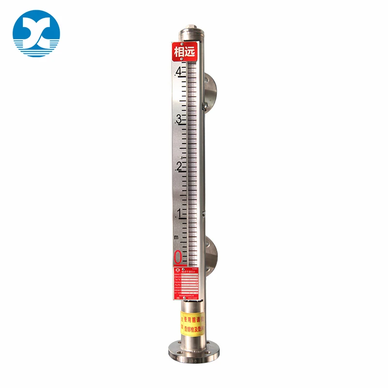
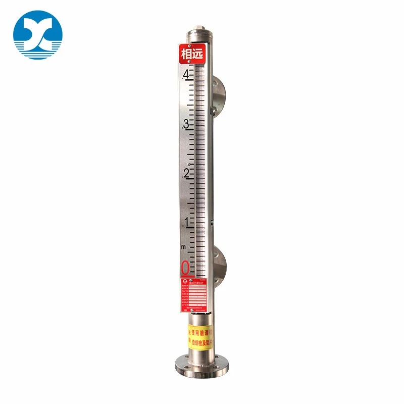
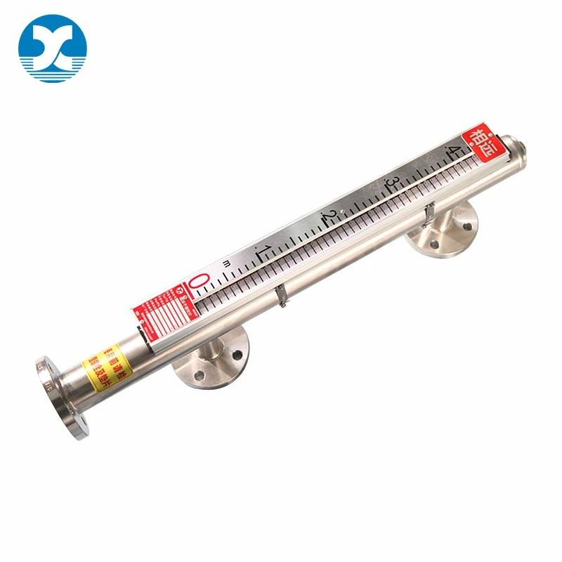
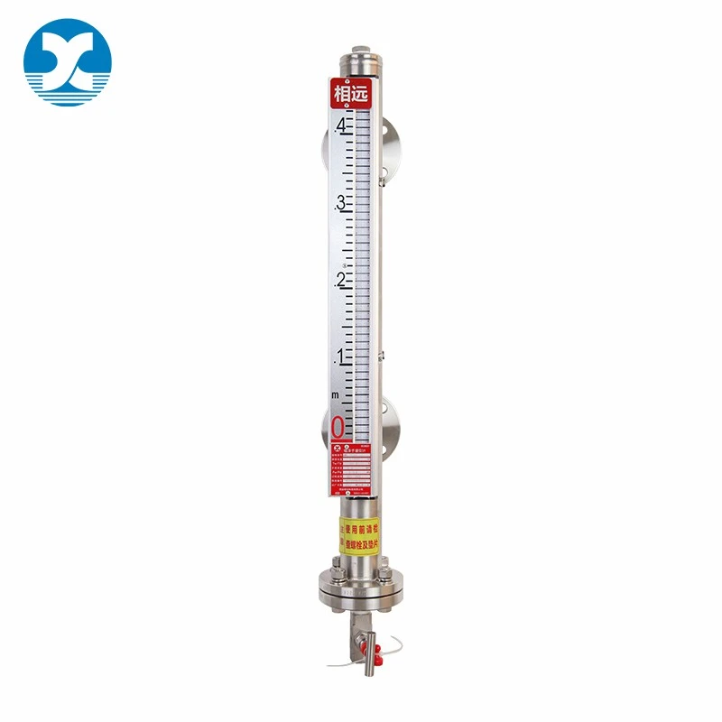
Why Choose Bypass Chamber Magnetic Level Gauge
- Serviceable Without Shutdown
Isolation valves let you remove the chamber for inspection or float replacement while the vessel stays in operation.
- Stable Readings in Turbulent Processes
The bypass chamber dampens surface agitation and foaming, delivering steadier level indication than direct-mount designs.
- High-Pressure, Code-Compliant Construction
Built to ASME B31.3 / B31.1, with 316SS or Titanium floats rated up to 320 bar for demanding oil & gas, power, and chemical applications.
- Seal-Free, Low Maintenance
Magnetic coupling eliminates dynamic seals at the indicator, reducing leak points and upkeep over the gauge's lifetime.
- Upgradeable Instrumentation
Add clamp-on transmitters or switches anytime - no process interruption required - for a simple path to remote monitoring.
- Custom-Engineered to Spec
Custom float weighting, concentric magnet design, and special materials available to match your exact media and operating conditions.
Key Features and Benefits
- Independent Bypass Chamber Structure
Separated bypass cavity buffers medium turbulence and pressure fluctuation for stable measurement. The gauge can be disassembled and maintained separately without draining tank liquid, cutting downtime and maintenance costs. Single-piece chamber supports a maximum measuring height of 5500 mm; multi-segment splicing is available for taller tanks.
- Extreme High Temp & High Pressure Resistance
Works steadily from -40°C to 400°C, covering PN16-PN250 and CLASS150-CLASS1500 pressure grades. Dual sealing options of PTFE (≤200°C) and metal graphite (≤400°C) deliver long-term leak-proof performance under harsh working conditions.
- Dual Measurement of Liquid Level & Liquid Interface
Realizes continuous level monitoring and layered interface detection. It adapts to media with minimum density of 0.4kg/dm³, and accurately identifies liquid layers with density difference ≥0.2kg/dm³ for oil-water separation and stratified storage tanks.
- Diversified Anti-Corrosion Wetted Components
Standard 304/316L stainless steel bypass chamber and flanges, with optional titanium float. Homogeneous matching materials effectively resist acid, alkali and chloride corrosion for chemical and petrochemical applications.
- Dual Magnetic Indication for All Temperature Scenarios
Low-temperature PA magnetic flaps (≤120°C) and high-temperature aluminum alloy flaps (≤400°C) are optional. Aluminum or stainless steel scales provide clear, direct on-site readings for operators.
- Global Standard Connection & Customizable Ports
Compatible with DN15-DN50 flanges, welding necks and threaded studs. Configurable top vent plugs and bottom drain valves facilitate regular exhaust and sediment cleaning on site.
Technical Specifications
Our bypass chamber magnetic level gauge adopts an independent separated bypass chamber structure, delivering reliable level and liquid interface measurement under extreme high temperature and high-pressure industrial environments. All structural components, wetted materials and connecting forms support flexible customization to match diverse chemical, petrochemical and energy process media. The table below lists all complete customized specifications and performance indicators for your model selection reference.
|
Parameter Item |
Technical Specification |
|
Pressure Rating Standard |
Industrial grade full pressure coverage: PN16 to PN250, ANSI Class 150 up to Class 1500 heavy-duty rating |
|
Operating Theory |
Bypass chamber communicating vessel principle, coupled with magnetic float magnetic induction display technology |
|
Available Measurement Modes |
Continuous liquid level monitoring / Dual-liquid interface layered measurement |
|
Installation Method |
Vertical center-to-center bypass external installation for industrial storage tanks |
|
Standard Measuring Height |
Single chamber integral type: maximum 5500mmUltra-high range: multi-segment combined structure for heights over 5500mm |
|
Bypass Chamber Outer Diameter |
Standard industrial sizes: 57mm and 60.3mm customizable |
|
Chamber Wall Thickness |
Dynamically configured based on actual pressure grade to ensure structural safety |
|
Field Connection Type |
High-pressure flange connection (DN15–DN50 / 1/2"–1-1/2", PN16–PN320 / 150#–1500#)Optional integral welding neck or threaded stud installation |
|
Top Vent Configuration |
Blank sealed type or R1/2" threaded plug vent assembly optional |
|
Bottom Drain Design |
R1/2" plug drain port or manual drain valve; customized structures supported |
|
Bypass Chamber Material |
Standard 304 / 316L stainless steel; special alloy materials available on demand |
|
Flange & Connection Material |
Homogeneous material matching the bypass chamber body for consistent thermal expansion |
|
Magnetic Float Material Grade |
Corrosion-resistant 316L stainless steel / high-performance titanium alloy float optional |
|
Continuous Working Temperature |
Wide temperature adaptation range: -40°C to +400°C |
|
Maximum Allowable Working Pressure |
16 bar minimum up to 250 bar full-pressure industrial grade |
|
Minimum Detectable Medium Density |
Stable measurement starting at 0.4 kg/dm³ |
|
Interface Measurement Threshold |
Effective layered detection requires liquid density difference ≥ 0.2 kg/dm³ |
|
Fastener Assembly Material |
Carbon steel / stainless steel bolt and nut sets for different working conditions |
|
Sealing Material Temperature Grade |
PTFE sealing compound: suitable for ≤200°C mediumMetal graphite composite seal: high-temperature resistant up to 400°C |
|
Indicator Support Frame |
High-temperature resistant aluminum alloy rail (full 400°C compatibility) |
|
Magnetic Display Component |
PA polymer flap (low-temp ≤120°C environments)Aluminum alloy magnetic flap (high-temp ≤400°C industrial conditions) |
|
Calibration Scale Material |
Durable aluminum alloy or stainless steel scale plate |
|
Internal Float Structure |
Fully welded, pressure-tight sealed cylindrical magnetic buoy |
|
Float Dimension Specification |
Float length professionally customized according to on-site medium density |
Typical Application Scenarios
- High-Pressure Steam Drum Monitoring (Power Generation)
In boiler feedwater and steam drum applications where operating pressure regularly exceeds 100 bar and temperatures approach 400°C, direct-mount level gauges often face float buoyancy instability and seal degradation. A bypass chamber design rated to ANSI Class 1500 with a 316L float and metal graphite sealing allows continuous, stable indication under these conditions while permitting chamber isolation during scheduled turnarounds - without draining the drum.
- Interface Detection in Oil-Water Separators (Oil & Gas)
For separator vessels handling crude oil and produced water with a density differential around 0.2–0.3 kg/dm³, standard single-float gauges frequently struggle to detect the interface reliably. A properly sized titanium or 316L float, matched to the specific density gap, enables clear layered-interface indication - supporting more consistent water-cut control and reducing manual dip-checks.
- Cryogenic to Moderate-Temperature Chemical Storage
Chemical storage tanks handling low-density media (down to 0.4 kg/dm³) across a wide temperature swing benefit from PA polymer flags in lower-temperature zones and aluminum alloy flags where localized heating occurs - avoiding the flag degradation seen with single-material indicator designs in mixed-temperature service.
- Retrofit on Existing Vertical Storage Tanks
Where vessel nozzle spacing already exists but access for maintenance is limited, the vertical center-to-center bypass mounting method allows straightforward retrofit onto legacy tanks, with multi-segment chamber construction accommodating measuring heights beyond 5,500 mm without requiring a single oversized chamber section.
Note: Scenarios above describe representative operating conditions this product line is engineered to address; specifications should be confirmed against your actual process data during selection.
Maintenance and Troubleshooting
Routine Maintenance
|
Task |
Recommended Frequency |
Notes |
|
Visual inspection of flag/follower rotation |
Monthly |
Confirm flags track float movement smoothly across full range |
|
Check top vent and bottom drain for blockage |
Quarterly |
Clear sediment buildup, especially in high-density or viscous media |
|
Inspect flange and fastener torque |
Annually or per turnaround schedule |
Re-torque per ASME B31.3/B31.1 bolted joint procedures |
|
Verify magnetic coupling strength |
Annually |
Test flag response with external magnet if float movement appears sluggish |
|
Chamber isolation valve function test |
Annually |
Confirm valves seat properly before relying on isolation for servicing |
Common Issues and Troubleshooting
- Flags Not Rotating or Showing Inconsistent Level
Usually caused by sediment or scale buildup inside the bypass chamber, particularly in high-density or particulate-laden media. Isolate the chamber via the top/bottom valves, drain through the bottom port, and inspect for internal fouling. For media with known scaling tendencies, increasing inspection frequency is recommended over redesigning the chamber.
- Float Not Responding to Actual Level Change
Check that the selected float density and dimensions match the actual process medium - a float sized for a different specific gravity than the real operating fluid is one of the most frequent causes of inaccurate readings after initial commissioning. This is also the most common issue after a process fluid change without corresponding float re-selection.
- No Clear Interface Reading in Dual-Liquid Service
Confirm the actual density difference between the two liquids meets the minimum 0.2 kg/dm³ threshold required for reliable layered detection. Below this threshold, interface readings may appear unstable even with correctly functioning hardware.
- Flag Discoloration or Sticking at High Temperature
Indicates flag material may be operating near or above its rated limit. PA polymer flags are suitable only up to 120°C; for higher-temperature zones, confirm aluminum alloy flags (rated to 400°C) were specified for that section of the gauge.
- Leakage at Flange or Vent Connections
Verify seal material matches the process temperature - PTFE seals are rated to 200°C; above this, metal graphite composite seals are required. Mismatched sealing material under thermal cycling is a common root cause of slow leaks at flanged connections.
Frequently Asked Questions
Q1: What's actually inside a bypass chamber that isn't in the tank itself?
The chamber is a standalone pipe section connected to the vessel through separate top and bottom nozzles - the float and magnetic coupling all live inside this external pipe, not inside the tank. That's the whole point of the design: you're measuring a column of liquid that mirrors the tank level, without putting any moving parts inside the vessel itself.
Q2: Do I need to shut down the tank to pull the float for inspection?
No, and this is really the main reason people choose a bypass chamber over a direct side-mount gauge. With isolation valves on both the top and bottom nozzles, you close them off, bleed the chamber down, and the float comes out for inspection or replacement while the tank keeps running. A side-mounted unit without that valve arrangement usually means draining or isolating the vessel itself to do the same job.
Q3: What's the minimum spacing required between the top and bottom nozzles on the vessel?
This depends on your measuring range and the vessel's nozzle schedule, but as a general rule the nozzle centers need to match your required measuring span plus enough margin above and below for the float's travel limits. We size this against your vessel drawing rather than using a fixed number - send us the nozzle locations and we'll confirm the chamber length works with your existing connections.
Q4: Can a bypass chamber be retrofitted onto a tank that already has an existing level gauge or sight glass nozzles?
Often yes, provided the existing nozzle spacing and rating are compatible with the chamber's process connections. This is actually one of the more common requests we get - replacing an old sight glass or mechanical float gauge with a bypass chamber magnetic unit using the same nozzle positions, which avoids cutting new openings into the vessel.
Q5: Does chamber diameter affect how fast the indicator responds to a level change?
Yes, to some degree. A larger-bore chamber holds more liquid volume relative to the flow path through the connecting nozzles, so on a fast-filling or fast-draining process there can be a slight lag between the actual tank level and what the chamber shows. For most storage and buffer tank applications this isn't noticeable, but for tanks with rapid level swings we'll size the nozzle bore accordingly during the proposal stage.
Q6: Why choose a bypass chamber instead of a direct side-mounted gauge in the first place?
The main tradeoffs come down to isolation and vessel penetration. A bypass chamber only needs two nozzle connections and can be valved off for maintenance without touching the vessel. A side-mounted gauge mounts closer to the vessel wall and is often simpler and cheaper, but usually doesn't offer the same isolation capability unless additional valving is added separately. If your process can't tolerate downtime for float servicing, the bypass chamber is generally the better fit.
Q7: Is chamber material selected independently from the vessel material?
Yes - the chamber and its wetted parts are specified based on your process media, not automatically matched to the vessel shell. It's common to see a carbon steel vessel paired with a 316L or Hastelloy bypass chamber where the level gauge sees concentrated or standing liquid that's more aggressive than what the bulk vessel wall is exposed to.
Q8: What happens at the isolation valves when the chamber is closed off - does that affect the tank process?
No. Closing the top and bottom isolation valves only cuts off flow between the tank and the chamber; the tank itself keeps operating normally. The liquid trapped in the chamber can then be drained through the bottom valve or drain connection for float removal, entirely separate from what's happening inside the vessel.
Q9: Can I add a transmitter or switch to the chamber without opening it up?
Yes - since the magnetic coupling passes through the chamber wall, clamp-on switches and reed transmitters mount externally on the chamber body itself. No need to break into the pressure boundary or drain the chamber to add remote monitoring later, which is a common phase-two upgrade after the visual gauge has been running for a while.
Q10: For tanks with agitators or high turbulence, does the bypass chamber still give a stable reading?
Generally yes, and this is another point in its favor over some in-tank float arrangements - because the chamber sits outside the vessel and is only connected through two relatively narrow nozzles, it naturally dampens the surface turbulence from agitation or mixing. The liquid inside the chamber settles to a much calmer level than what's happening at the tank's liquid surface.
Ready to Specify the Right Bypass Chamber Magnetic Level Gauge for Your Application?
Every process has its own combination of pressure, temperature, medium density, and installation constraints - and getting the float, chamber material, and sealing selection right the first time matters for long-term reliability. Share your operating conditions with our engineering team, and we'll help you configure a solution matched to your exact requirements, whether it's a standard configuration or a fully customized design.
Hot Tags: bypass chamber magnetic level gauge, China bypass chamber magnetic level gauge manufacturers, suppliers, factory, level measurement, Side Mounted Stainless Steel Magnetic Level Gauge, sonar tank level sensor, Top Mounted PP Magnetic Level Gauge, Top Mounted Stainless Steel Magnetic Level Gauge, water level float gauge


